A multimeter can look intimidating: a dial full of symbols, several input ports, two pointed probes, and a display that sometimes says “OL” instead of a number. But for most beginner jobs, you only need to understand three functions, voltage, continuity, and resistance. A multimeter doesn’t repair anything by itself, it tells you whether power is present, whether a path is broken, or whether a component has the resistance it should. Start with safe, low-voltage examples before ever attempting household electrical testing, and know that everything here covers digital multimeters, since that’s what most readers will own.
To use a multimeter: plug the black lead into COM, put the red lead into the V/Ω port for voltage, continuity, and resistance, turn the dial to the correct function, then place the probes on the correct test points. Do not test continuity or resistance on a live circuit, and never measure voltage with the red lead in an A or mA current jack.
Beginner quick start:
1. Black probe goes into COM.
2. Red probe goes into V/Ω for voltage, continuity, resistance, diode, and most beginner tests.
3. Choose V⏢ for DC voltage, such as a car battery.
4. Choose V~ for AC voltage, such as an outlet.
5. Choose the sound-wave/diode symbol for continuity.
6. Choose Ω for resistance.
7. Never test resistance or continuity on an energized circuit.
8. Never put the red lead in the A or mA port when measuring voltage.
Multimeter Safety Rules

This comes first, not as an afterthought. Inspect the meter body, probes, insulation, connectors, and lead tips before every use, and never use a cracked meter, damaged insulation, a loose probe connection, or exposed wire. Confirm the meter’s CAT rating and maximum voltage rating actually suit the job, use leads rated equal to or greater than the meter and the environment, and keep fingers behind the probe guards at all times.
Select the expected function and range before touching a circuit. If you’re using a manual-ranging meter and the voltage is unknown, start at the highest range. For voltage checks, black lead into COM, red lead into V/Ω, and never measure voltage with the red lead plugged into the A or mA terminal. Turn off, unplug, isolate, and discharge a circuit before measuring continuity or resistance, and verify the meter on a known source before trusting a zero-voltage reading on a circuit you believe is dead. Avoid working alone on energized systems, keep the work area dry, and if you’re unsure at any point, stop and call a qualified electrician.
The CAT rating describes how well a meter withstands transient overvoltage in a specific environment, it’s not simply a measurement of normal operating voltage. CAT I is intended for low-energy circuits not directly connected to mains, CAT II is used around plug-in loads, CAT III covers fixed installations, and CAT IV is for service-entry or utility-side environments.
| Rating | Typical Environment | Beginner Example | Household Panel Work? |
|---|---|---|---|
| CAT I | Isolated low-voltage electronics | Batteries, hobby circuits, small DC devices | No |
| CAT II | Plug-in loads and appliances | Appliance cord, outlet-connected device testing | Not for inside a main panel |
| CAT III | Fixed building wiring and distribution | Permanently installed circuits, distribution equipment | Only with relevant training and safe procedures |
| CAT IV | Service entrance and utility supply | Meter bases, overhead/underground service lines | Not a beginner task |
A higher CAT rating doesn’t make any task automatically safe. It only means the meter is designed for a more demanding transient environment when used correctly.
Know Your Multimeter Parts
The Display
Look for the numeric reading, a unit symbol, a minus sign, “OL” or an overload indicator, a low-battery icon, an auto-range indicator, an AC/DC indicator, and a continuity beep indicator.
The Dial
| Symbol | Meaning | Typical Beginner Use |
|---|---|---|
| V⏢ or VDC | DC voltage | Car batteries, AA batteries, USB power, low-voltage devices |
| V~ or VAC | AC voltage | Household outlets and AC-powered appliances; higher risk |
| Ω | Resistance | Checking resistors, heating elements, coils, wiring on a dead circuit |
| Sound-wave / speaker symbol | Continuity | Checking fuses, wires, switches, connections on a dead circuit |
| A⏢ / ADC | DC current | Advanced, requires moving the red lead and opening the circuit |
| A~ / AAC | AC current | Advanced, use only as the manual instructs |
| Diode symbol | Diode test | Basic electronics and some automotive checks |
| Hz | Frequency | Advanced diagnostics |
| Capacitance symbol | Capacitance | Capacitor testing, only after safe discharge |
| Temperature symbol | Temperature | Available only on some models with a probe |
Symbols and jack labels vary by brand, always check your specific meter’s manual before using a function not covered here.
The Ports
| Port | Usually Labeled | What It’s For | Beginner Default? |
|---|---|---|---|
| Common port | COM | Black lead for nearly every measurement | Yes |
| Voltage/resistance port | VΩ, VΩHz, or similar | Red lead for voltage, continuity, resistance, diode, frequency | Yes |
| Low-current port | mA, µA | Small current measurements | No, avoid until you understand current testing |
| High-current port | A or 10A | Higher current measurements | No, avoid until you understand current testing |
For nearly every beginner measurement, use COM for black and V/Ω for red. Move the red lead to the A or mA jack only when deliberately measuring current and following your meter’s manual.
How to Set Up a Multimeter
- Turn the meter on.
- Inspect the display for a low-battery warning.
- Insert the black test lead into COM.
- Insert the red test lead into V/Ω.
- Select the test function.
- If the meter is manual-ranging, choose a range above what you expect to measure.
- Inspect the probe tips and leads again.
- Test the meter on a known safe source where appropriate.
- Touch only the insulated parts of the probes.
- Record the reading before moving probes.
For a potentially hazardous “is this circuit dead?” test, professionals use a live-dead-live approach: test the meter on a known live source, test the circuit believed to be de-energized, then test the meter again on the known live source. This confirms the meter didn’t fail or lose connection partway through the check.
How to Measure DC Voltage
DC voltage is used by batteries and many vehicle electrical systems. The reading may show a minus sign if probe polarity is reversed, and a negative reading on a battery test isn’t automatically a fault, it usually just means the red and black probes are swapped.
Example: Test an AA Battery
- Set the dial to V⏢.
- Choose a range higher than the battery’s expected voltage if using manual range.
- Place the black probe on the flat negative end.
- Place the red probe on the positive button end.
- Read the display.
- Reverse the probes briefly to see the sign change, not the actual voltage.
Battery condition depends on chemistry, load, and manufacturer guidance, not a single hard “replace at X volts” rule.
Example: Test a 12V Car Battery
- Turn the vehicle off and switch off major accessories.
- Set the meter to DC voltage.
- Use a range above 12V if manual-ranging.
- Touch black probe to the negative battery terminal.
- Touch red probe to the positive terminal.
- Read the voltage.
- Compare against the battery maker’s guidance or a proper load test rather than diagnosing battery health from voltage alone.
A resting voltage reading is a useful first check, but it doesn’t fully prove a car battery is healthy. Battery condition also depends on load performance, charging system behavior, temperature, and state of charge. Need a meter mainly for vehicle work? See our guide to the best automotive multimeters.
How to Measure AC Voltage
Warning: Testing household outlets and mains-connected equipment can expose you to hazardous voltage. If you don’t understand meter ratings, probe placement, and basic electrical safety, don’t attempt this test. Use a qualified electrician instead.
This isn’t meant as a primary beginner exercise, it’s here for readers with a suitably rated meter and a genuine reason to test.
- Confirm the meter and leads are rated for the environment.
- Black lead into COM, red lead into V/Ω.
- Turn the dial to V~.
- If manual-ranging, select a range above expected mains voltage.
- Keep fingers behind probe guards.
- Insert probes carefully without letting the metal tips touch each other.
- Read the display.
- Remove the live/red probe first, then the common/black probe, per your manual’s guidance.
The expected reading depends on your country’s nominal supply voltage, consult local electrical standards and a qualified electrician if a reading looks unexpected. Do not open electrical panels or test service equipment as a beginner.
How to Test Continuity

Continuity testing checks whether electricity can travel through a wire, fuse, switch, or connection. On most digital multimeters, a beep means the circuit path is complete. Test continuity only on a circuit that’s turned off, unplugged, and verified de-energized.
- Disconnect power from the circuit or device.
- Remove batteries if possible.
- Discharge capacitors where applicable.
- Put black lead in COM and red lead in V/Ω.
- Turn the dial to continuity mode.
- Touch the two probe tips together to confirm the meter beeps or reads near zero resistance.
- Touch one probe to each end of the wire, fuse, switch, or connection.
- Listen for the beep and read the display.
- If no beep occurs, the path may be open, but verify the component and test points before concluding it’s failed.
A continuity beep indicates a closed path where electricity can flow, no beep indicates an open or broken path.
Test a Blade Fuse
Remove the fuse from the circuit if possible, touch one probe to each metal contact. A beep or near-zero resistance usually indicates continuity; no beep or OL generally indicates an open fuse. Never replace a blown fuse with a higher-rated one.
Test an Extension Cord
Unplug it from the wall, check each conductor end-to-end, and check for unintended continuity between conductors if the cord design permits safe access. Replace damaged cords rather than casually taping mains cords.
Test a Switch
Disconnect power, then test continuity across the switch terminals in both ON and OFF positions. Terminal arrangement varies by device, verify against the device’s diagram.
How to Measure Resistance
Resistance is opposition to electrical flow, measured in ohms. It’s useful for checking components and verifying whether a wire or circuit path is open.
Never measure resistance on a powered circuit. Disconnect power and discharge stored energy first, otherwise you risk damaging the meter, damaging the circuit, or creating a shock hazard.
- Turn off and isolate power.
- Remove the component from the circuit when possible, or isolate at least one side to avoid parallel paths.
- Black lead into COM, red lead into V/Ω.
- Turn the dial to Ω.
- Select a suitable range if manual-ranging.
- Touch probes to the two component terminals.
- Read the result.
- Compare it to the component’s actual specification, not a random internet “normal range.”
| Display Reading | Common Meaning | What to Do |
|---|---|---|
| Near 0 Ω | Very low resistance / near-continuous path | Normal for a good wire or closed switch |
| Specific numeric value | Measured resistance | Compare with component specification |
| OL / 1 / overload | Above selected range or circuit is open | Increase range if manual-ranging; verify connection |
| Reading changes gradually | Component may be charging or stabilizing | Wait briefly; check component type |
| Unstable reading | Poor probe contact, dirty contact, or component behavior | Re-test with clean, stable contacts |
How to Test a Car Battery
A voltage reading checks present terminal voltage. It does not replace a load test, does not fully diagnose the alternator, and can’t reliably determine every battery issue on its own.
Vehicle Off
Use the DC voltage method described above. There’s no single universal pass/fail figure that applies regardless of battery type and condition, don’t treat one as gospel.
Engine Running
Alternator-output testing requires real care: keep hands, clothing, leads, and cables away from belts, fans, and moving parts, and use your vehicle’s service manual for expected charging-system values. If you see an unexpected result, that’s a reason for further diagnosis, not an immediate replacement decision.
What to Check Next
Battery terminals, corrosion, loose cable connections, battery age, warning lights, starting symptoms, and ultimately a professional battery and charging-system load test if the picture is unclear.
How to Test a Fuse
The continuity method above is the safest approach: remove the fuse if possible, test in continuity mode, a beep means it’s likely intact, no beep means it’s likely open. Testing a fuse in-circuit with voltage is possible but introduces live-circuit risk and depends on the circuit being powered, treat that as an advanced technique, not a beginner default. A blown fuse is usually a symptom, not the root cause, find the underlying overload, short, or failed component before just replacing it.
How to Test a Wall Outlet
If the outlet is loose, warm, discolored, cracked, wet, damaged, or repeatedly trips a breaker, stop. Don’t troubleshoot it with a basic multimeter, contact a qualified electrician.
Keep this brief: confirm a suitable CAT rating, set to AC voltage, use COM and V/Ω ports, use probes correctly, never touch exposed conductive surfaces, never use damaged leads, and avoid working alone. Refer to local electrical standards for expected values and outlet configuration. If you only need to know whether voltage is present at all, rather than a full diagnostic reading, our best voltage testers guide and how to use a voltage tester pen cover a simpler, often safer tool for that specific question.
What “OL” Means on a Multimeter
“OL,” “1,” or an overload indication can mean different things depending on the selected function.
| Selected Mode | What OL Commonly Means |
|---|---|
| Resistance | Open circuit or resistance above selected range |
| Continuity | No continuous path detected |
| Voltage (manual-range meter) | Selected range may be too low |
| Current | Circuit or measurement setup is outside the selected limit |
| General | Consult your meter’s manual, displays differ by model |
“OL” is not a diagnosis by itself. Always interpret it together with the selected function, range, where the probes are connected, and whether the circuit is powered or isolated.
Don’t Start With Current Measurement
Current testing is more advanced because it often requires moving the red lead into a current jack, opening the circuit, connecting the meter in series, staying below the meter’s fused input limit, and selecting the correct range and fuse. A beginner who sets a multimeter to current mode and connects it directly across a battery or outlet, the way you would for voltage, can create a short circuit, blow the meter’s internal fuse, damage the meter, or create a real hazard. Learn DC voltage, continuity, and resistance first. When you actually need current measurement, follow the exact procedure in your meter’s manual, or use a clamp meter where appropriate instead.
Common Multimeter Mistakes
- Putting the red lead in the A or mA jack when measuring voltage.
- Testing continuity on a live circuit.
- Testing resistance on a powered circuit.
- Selecting AC when measuring a battery, or DC when measuring an outlet.
- Using a damaged probe or cracked insulation.
- Ignoring CAT and voltage ratings.
- Touching the metal probe tip during a measurement.
- Starting on too low a range with a manual-range meter.
- Testing a component while it remains connected in a complex circuit.
- Assuming a battery is healthy from voltage alone.
- Using a cheap, unsuitable meter in a higher-energy environment.
- Measuring current without understanding the meter often must be connected in series.
- Forgetting to return the red lead to V/Ω after a current measurement.
- Using a continuity beep alone as proof a component is good.
- Working around live mains circuits when you aren’t qualified.
Five Multimeters Worth Considering
1. Klein Tools MM325 – Best Overall for Beginners
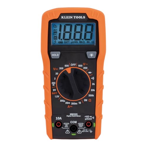
A manual-ranging meter measuring AC/DC voltage, DC current, and resistance, and testing batteries, diodes, and continuity. Klein’s Lead Alert feature uses LEDs to warn you if the leads are in the wrong port before you take a reading, a genuinely useful beginner safety check that catches the single most common multimeter mistake before it happens. Built to withstand a 6.6-foot drop, with a backlit display for low light.
What to know honestly: this is manual-ranging, not auto-ranging, you’ll need to select an appropriate range yourself rather than have the meter do it automatically. It’s also not a substitute for a high-end professional meter, and you should verify its exact CAT rating and intended environment from Klein’s current listing before relying on it for anything beyond the basics.
2. Fluke 117 – Best Premium Upgrade for Homeowners
No products found.Genuinely auto-ranging, with automatic AC/DC voltage selection and a built-in AutoV/LoZ mode that helps prevent false readings from “ghost voltage.” Non-contact voltage detection lets you check for live voltage without even touching the probes to a conductor, and true-RMS measurement gives more accurate readings on non-standard electrical loads than a basic meter provides.
What to know honestly: this costs substantially more than entry-level meters, and it’s unnecessary if you only test AA batteries and the occasional automotive fuse. It earns its price if you’ll genuinely use a multimeter often, not just once or twice.
3. Innova 3320 – Best for Beginner Mechanics

Auto-ranging and built specifically around automotive and household troubleshooting, with color-coded LEDs (green, yellow, red) for a quick battery condition check and a 10 megaohm input rated safe for household outlets, fuses, wiring, and vehicle batteries and charging systems. Attachable test leads and a stand allow hands-free use, genuinely useful when you’re working under a hood alone.
What to know honestly: a multimeter, including this one, can’t fully diagnose a battery, alternator, or modern vehicle network by itself. For deeper automotive diagnostics, you’ll eventually want a scan tool, a proper battery load tester, or a clamp meter alongside it.
4. Klein Tools MM400 – Best Value Step-Up

The genuinely auto-ranging model in Klein’s lineup, adding capacitance, frequency, duty-cycle, diode, continuity, and temperature measurement on top of standard AC/DC voltage and current, at a meaningfully lower price than a premium Fluke.
What to know honestly: more functions can make a meter more confusing for a total beginner, if this is your very first meter, keep your actual first-use practice focused on voltage, continuity, and resistance regardless of what else the dial offers.
5. Fluke 87V – Best for Serious Mechanics and Advanced Users

An industrial-grade meter built for advanced troubleshooting, measuring up to 1000V AC/DC with peak min/max capture and a low-pass filter for accurate readings on variable-frequency drives and other noisy electrical environments. This is the meter professionals reach for when diagnosing motor drives, plant automation equipment, and demanding automotive charging or sensor faults.
What to know honestly: this is overkill for most first-time users, and its advanced functions won’t make a beginner safer if the fundamentals haven’t been learned first. Buy it for frequent, demanding use, not for testing household batteries.
For a deeper look at professional-tier options beyond these five, see our best professional digital multimeters guide.
Frequently Asked Questions
What setting should I use on a multimeter to test a battery?
Use the DC-voltage setting, usually shown as V with a straight line and a dashed line. Put the black lead in COM, the red lead in V/Ω, and choose a range higher than the expected voltage if your meter isn’t auto-ranging.
What does OL mean on a multimeter?
“OL” generally means overload or open loop. In resistance or continuity mode, it often means the circuit path is open or resistance is outside the selected range. The exact meaning depends on the selected function and your specific meter model.
Can I test continuity with the power on?
No. Turn off, unplug, isolate, and verify the circuit is de-energized before testing continuity. Continuity mode sends a small test signal from the meter and isn’t intended for live circuits.
Which port does the red multimeter lead go into?
For voltage, continuity, resistance, and most beginner tests, insert the red lead into the port marked V/Ω, VΩHz, or similar. Put it in the A or mA port only when intentionally measuring current, following your meter’s manual.
Why does my multimeter show a negative voltage reading?
On DC measurements, a negative reading usually means the red and black probes are reversed relative to polarity, this commonly happens when testing a battery with the red probe on negative and black probe on positive.
Can a multimeter test a car battery?
Yes, it can measure battery voltage. Voltage alone, however, doesn’t prove the battery is healthy under load or that the vehicle’s charging system is working correctly, a load test and charging-system diagnosis may still be needed.
Can I test a wall outlet with any multimeter?
No. Use only a meter and test leads with an appropriate CAT rating and voltage rating for the environment. Testing household mains presents a real shock and arc hazard, if you’re unsure, contact a qualified electrician.
What is the easiest multimeter for a beginner to use?
An auto-ranging digital multimeter with clearly labeled ports, a continuity beep, DC and AC voltage functions, resistance, and appropriate safety ratings is generally easiest. The Innova 3320 is a practical, genuinely auto-ranging entry point for DIY automotive work specifically.
A multimeter is one of the first add-ons most beginner mechanics need – see our guide to the best mechanic tool set for beginners for the full starter foundation.